
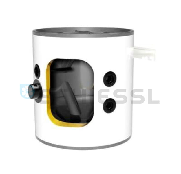


Bitzer BÞndelrohr-VerflÞssiger, K033N-2/4 Pass
Popis zboÅūÃ:
Weitere Informationen (DE)
Design safety
Certified according to the European Pressure Equipment Directive 2014/68/EU
Design features
- Heat exchanger pipes: made from Cu or Cu-Ni (saltwater resistant version) with newly developed pipe geometry and a âlow foulingâ profile on the cooling medium side
- Heat exchanger pipes are soldered into breaker plates to ensure a secure seal
- mantle pipes and breaker plates made from pressure vessel steel P 265 GH
- Recirculating cap:
- removable, allows pipes to be mechanically cleaned
- connection and deflecting side interchangeable
- cooling medium outlet from K573H(B)
- additional bleeding plugs from K38 03T(B) - Breaker plates with plastic coating
- Cooling medium connections: Threaded pipe or flange
- inspection glass as standard
- Mounting brackets
- bottom: vessel labelled as âNâ
- top and bottom: vessel labelled as âHâ (for installing single compressors) and âTâ (for single and tandem compressors) - Refrigerant connections
- pressurised gas: Rotalock adapter/solder connector with flange K1053H(B) and above
- refrigerant outlet: shut-off valve
- alternative refrigerant outlet from model K123HB - Rotalock connections for pressure relief valve
- inner thread 3/a'' -18 NPTF
- outer thread 1 žâ - 12 UNF - suitable for (H)CFC / HFC refrigerants (refrigerants with a temperature glide > 2 K on request)
- Maximum permitted pressure/temperature
- refrigerant side: 28 bar / -10 °C to 120 °C
- cooling medium side: 10 bar / -10 °C (with antifreeze agent) to 95 °C - inert gas filling
bundled pipe condensers with refrigerant outlet at the bottom can also be used as pressurised gas desuperheaters.
Special versions:
- Salt water resistant version:
- Cu-Ni pipe, recirculating cap with plastic coating - recirculating cap with plastic coating for standard version with Cu pipes
- mounting rails or plates (e.g. for installing compressor)
- adapter for connecting the pressure relief valve on all models
- threaded or welding neck flange
- refrigerant inlet and outlet with various adapter and valve combinations
- conforms to foreign regulations and various certification societies (e.g. Bureau Veritas, Germanischer Lloyd, Lloyd's Register of Shipping)
Scope of delivery / accessories
4-pass design corresponds to standard version
Performance data
The specified compressor performance is based on valves measured at a pressurised gas temperature of 90 °C and a cooling medium cleanliness factor r= 0.4 x 1 o-4 m2 K/W.
Condenser design
Calculating of condenser capacity Q
When selecting a condenser it is first necessary to determine the condenser capacity Q. Condensing capacity can be calculated in two different ways:
Condensing capacity as the sum of the refrigeration capacity and power consumption
This method adds together the refrigeration capacity and power consumption of the compressor (or compressors in a power rack). Performance data can be found in the compressor information leaflets or in the software.
Estimation using factors
A simplified method can also be employed for typical designs. To determine condensing capacity, the refrigeration capacity of the compressor is multiplied by the factor in the following diagram.
Â

- RostlinnÃĄ ÅĄkolka
- Les
- Outdoor
- PlastovÃĐ navijÃĄky
- E-SHOP
- AM studio
- Schiessl formulÃĄÅ poptÃĄvka
- Schiessl rozcestnÃk
- MB podkategorie
- tes svÃĐvolnÃĐ mazÃĄnà blokÅŊ
- Myslivost
- 01.DunstabzÞge
- 50ccm.cz
- SpoleÄenskÃĄ Äinnost
- kalendÃĄÅ
- PomÃĄhajà nÃĄm
- pravÃ― sloupec
- bloky
- Fotogalerie
- odkaz ven
- test pred
- test modul
- Lov
- Mapa strÃĄnek
- Registrace eshop
Created by ÂĐ 2016 ALS Euro s.r.o. tvorba www strÃĄnek & webdesign